Utilising new integrated additive manufacturing and investment casting facilities, William Cook Cast Products has produced a complex valve cage casting made of a cobalt-based alloy that is notoriously demanding to produce. The valve cage can withstand corrosion and erosion in an aggressive chemical environment and was previously thought to be uncastable.
Component
- Valve cage, net weight 70kg (finished condition), 220kg (as-cast)
- Varied geometric range – from 3mm thickness in the small windows to 80mm at each end
- Overall part size – 595mm (long) x 390mm (diameter)
Alloy
- Cobalt alloy 6B
Customer Requirements
- Good as-cast form and finish – with no weld-repair
- Good surface finish
Previous Part
- Several stacked, laminated plates, machined to profile to form individual layers
Outcome
The conversion to a casting enables the customer to be able to take advantage of:
- Lower overall cost
- Unconstrained design i.e. design for purpose not design for manufacture
- Reduced lead-time compared with the conventional manufacturing route
- Freedom of alloy choice
Challenges
- Complications arising from the size and complexity of the casting
- Thick sections immediately adjacent to thin sections, creating wide-ranging boundary conditions to address when filling and feeding the part
- Cobalt alloy 6B is a notoriously demanding alloy to produce because the strength and hardness of the structure, derived from the fine carbide particles dispersed throughout the matrix, make it particularly susceptible to cracking both during solidification and during processing.
- Pouring temperature: too high a pouring temperature leads to non-metallic inclusions and, due to the high thermal mass of the casting, increases the risk of mould breakdown during solidification; too low a pouring temperature results in an incomplete fill or the formation of cold laps in the upper levels of the casting.
- Consideration had to be given during methoding to minimising the potential for high residual stresses during cooling, which could lead to cracks
Method
- The part was 3D modeled. Filling and solidification simulation software was used to compare different casting orientations. Feed pathways and pouring methods were optimised to produce the highest integrity and highest yield design possible.
- A horizontal cage with a feeder head at each end was used. Metal was introduced directly down the feeder head at each end, using two ladles simultaneously, to minimise heat losses in the liquid metal whilst filling the mould.
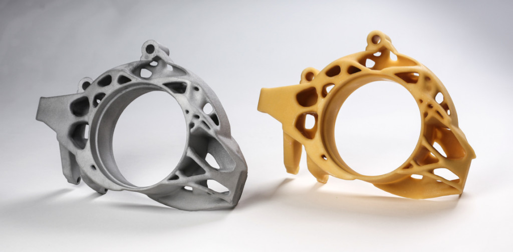
- The pattern was printed in polymethyl methacrylate (PMMA) – a substitute for the wax traditionally used in the investment casting process. This is an additive process resulting in a 3D profile with a high degree of accuracy. Once fully cured, the PMMA pattern was dipped into a very thin paraffin wax mixture to seal any porosity in the PMMA pattern surface, allowing the ceramic slurry to bond to the surface of the wax without penetrating it. The completed pattern is then coated in ceramic using an alumino-silicate shell system, in exactly the same way as wax patterns from traditional dies. However, the large size of the part presented an additional challenge.
- The PMMA was then removed from the shell using a William Cook proprietary technique, which mitigates the problems with cracking of the mould.
- The mould is washed out to remove any residue.
- The mould was buried in sand and the shell mould preheated locally using portable heaters prior to pouring.
- Melting was undertaken in an electric induction furnace and the metal was poured from two teapot ladles simultaneously.
- Cold cutting techniques were employed for the removal of the feeder heads to ensure that the potential for cracking was minimised.